The application SW “MER vs. CARRIER”, available opt. for ROVER HD series is a valuable aid in the search for possible causes of interference in the reception of a digital TV signal.
Often, the Access Point Wi-Fi transceivers, repeaters, AUDIO-VIDEO remote control repeater, ballasts for lamps, street lighting, etc., inside the apartment or in the vicinity can be a source of trouble and cause poor reception of some channels; sudden “pixellation image”, interruptions, etc. A thorough analysis of the channel by using “MER vs CARRIER” measure, allows you to analyze the trend of the MER value of all individual carriers that make up a digital terrestrial channel.
In Figure 1, we show the measurement screen of a digital terrestrial TV channel where the main parameters of receiving power (POWER) – Modulation Error Ratio (MER) – Signal to Noise Ratio (SNR) – Noise Margin (NsMAR) – errors before correction Viterbi (bBER) and after (aBER) represented a single screen, turn out to be correct.
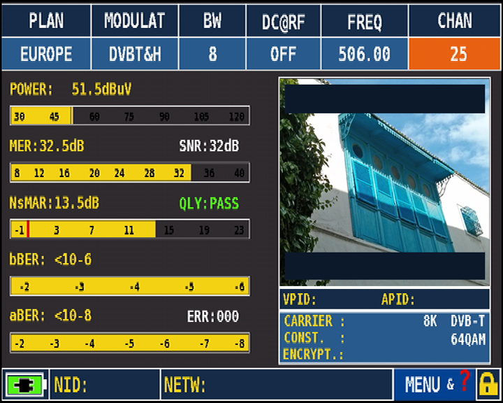
Figure 1: MEASURES without interference
Now, we simulate signal interference in the laboratory. As can be seen in Figure 2 measurement parameters remained almost unchanged with the exception of the parameter for errors before Viterbi (bBER) which is down sharply from to 1 x 10⁻².
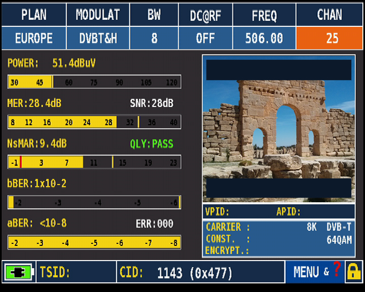
Figure 2: Interfered TV channel
Given that the interference simulated in the laboratory to the signal is not related to issues of ECHOES, pressing SPECT to analyze the spectrum of the received channel, at first glance do not appear to present a significant noise sources. His “Shape”, Figure 3, it would seem proper, the shoulders are Sharp and the upper part is linear. Usually, it corresponds to a signal having good reception parameters.
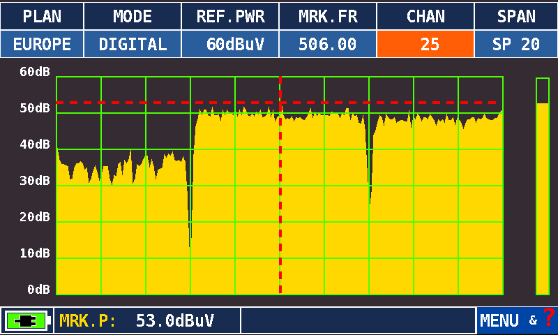
Figure 3: Spectrum TV SPAN 20 MHz
By pressing the TV key or the MEAS, depending on the model of your instrument, in succession after viewing the screens relative to CONSTELLATION and the analysis of the Impulse Response (ECHOS) screen appears MER versus CARRIER, Figure 4. On the screen it is possible to analyze how the value of MER is not constant for all the carriers that make up a signal DIGITAL TV DVB-T 8K, from the number 0 to the number 6816, but falls considerably at a point. Selecting with the encoder the MARKER item you can select the area of the carriers (CARRIER) affected by the disorder (destroyed): for example, the number 1618. At the bottom left of the screen is detected as the value of MER measured by the instrument for carrying selected to be folled to 12 dB. In addition, the screen is represented by a blue line AVERAGE MER value measured in the whole channel (RMS) of about 28 dB. This value is also shown on the main mesurements of the instrument, Figure 2, where you will find all the main measures and the image of the selected channel.
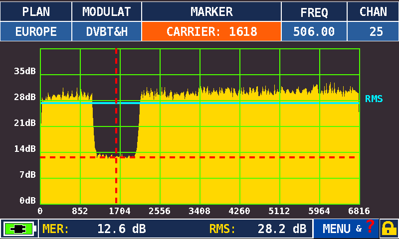
Figure 4: Display the NORMAL MER vs. CARRIER
Selecting the MENU function (bottom right), Figure 5, you can perform a ZOOM setting of the carriers in the value START and STOP CARRIER, of the desired values: for example, START N. 800 CARR, Carrier, and STOP at N. 2500 CARR, Carrier.
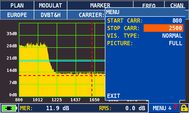
Figure 5: MER vs. CARRIER – Menu selection START / STOP CARRIER
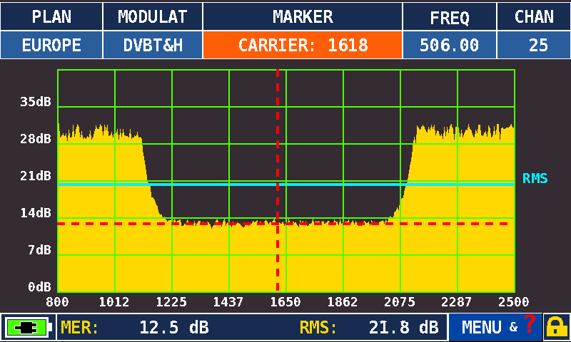
Figure 6: MER vs. CARRIER – Display carriers ZOOM between 800 and 2500 – NORMAL Mode
Besides the possibility to select one of the carriers ZOOM, you can also choose the display mode: VIS. TYPE: NORMAL or REVERSE. To make your choice, select the MENU and choose the desired display mode, Figure 7.
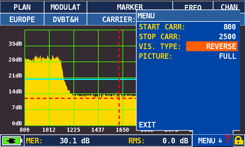
Figure 7: Menu Selection display NORMAL/REVERSE
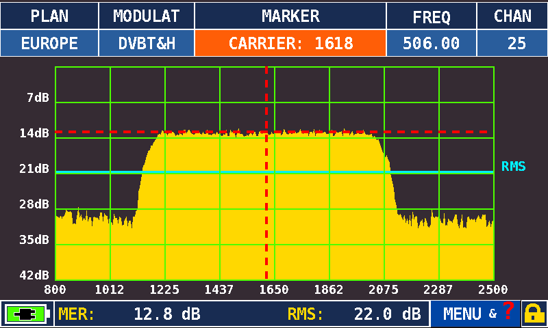
Figure 8: MER vs. CARRIER ZOOM display between the carriers 800 and 2500 – REVERSE mode
Now, if there was the option to turn off the signal from the TX (in our example, channel 25) and maintain the interference simulated in the laboratory, in the mode spectrum we have the ability to view only the source of isturbance. In Figure 9 is shown the source of the disturbance applied to the channel in the laboratory that has caused the destruction of the value of the MER for a given section of carriers, thereby decreasing considerably the value of bBER.
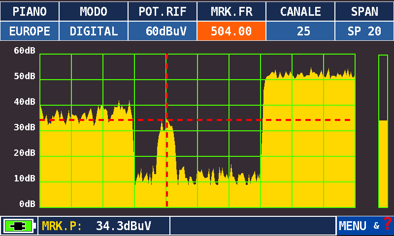
Figure 9: Spectrum TV – Interference Only – SPAN 20 MHz
In the spectrum shown in Figure 3, this interference was not possible to display it as hidden under the received signal. Only in the case where the source of interference had a higher intensity of the received signal, then even-mode spectrum would be possible to display it, a bit as it was during the cohabitation between analog and digital signals, Figure 10.
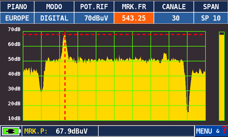
Figure 10: Spectrum TV – Cohabitation channel DIGITAL and ANALOG – SPAN 10 MHz
Note: