Below we listed the procedures to perform POWER AND OPTICAL ATTENUATION MEASUREMENTS:
 |
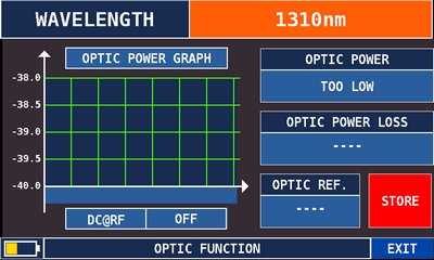 |
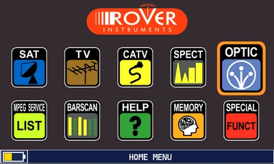
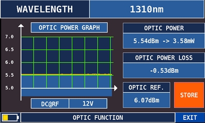
| Touch “OPTIC” from the HOME screen; | Touch “WAVELENGTH” and select the required wavelength, for example “1310nm”; |
 |
 |
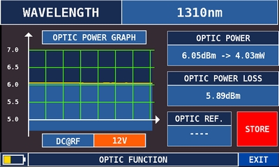
| Touch “DC@RF” and select, if it is required, the power supply voltage: for example “12V” (Volt); |
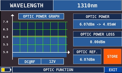
Touch “STORE” and store the measured optical power value (OPTIC REF.): for example “6,07 dBm”; |
 |
|
| The “OPTIC POWER LOSS” field shows the optical attenuation value compared to the stored value (Optic REF): for example: “-0,53 dBm” (OPTIC REF. 6.07dBm less OPTIC POWER 5.54dBm uqual OPTIC POWER LOSS -0.53dBm). |
|
Below we listed the procedures to perform OPTICAL INPUT RF MEASUREMENTs & SPECTRUM:
 |
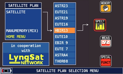 |
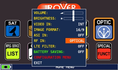
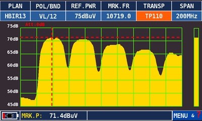
| Touch “RF IN” and select “OPTICAL” from the volume screen; | In SAT mode press the“PLAN ” key, select the satellite required, then “SPECT” to visualize the spectrum; |
 |
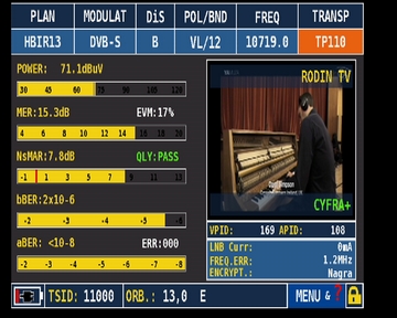 |
| SAT spectrum; | Press the “SAT” or “MEAS” key to carry out the measurements (depending on the model of instrument used). |
FIBER OPTIC and REMOTE POWER SUPPLY CABLE CONNECTION example:
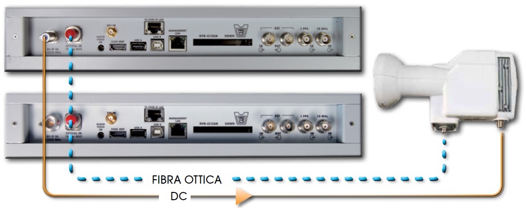
Important: In OPTIC model it is possible to analyze the spectrum and measure only Vertical/Low band (VL) transponders.
Note: