Important: Do not use glue to secure the flat cable into the connector, it will irreparably damage the instrument.
If the instrument are having trouble viewing the display as listed on the title, check the correct insertion of the “flat cable of the display” in the connector of the motherboard.
Important: Do not move or enter the FLAT CABLE DISPLAY in its connector while the instrument is POWER ON.
A ) Turn off the instrument;
B ) Remove the instrument from the bag;
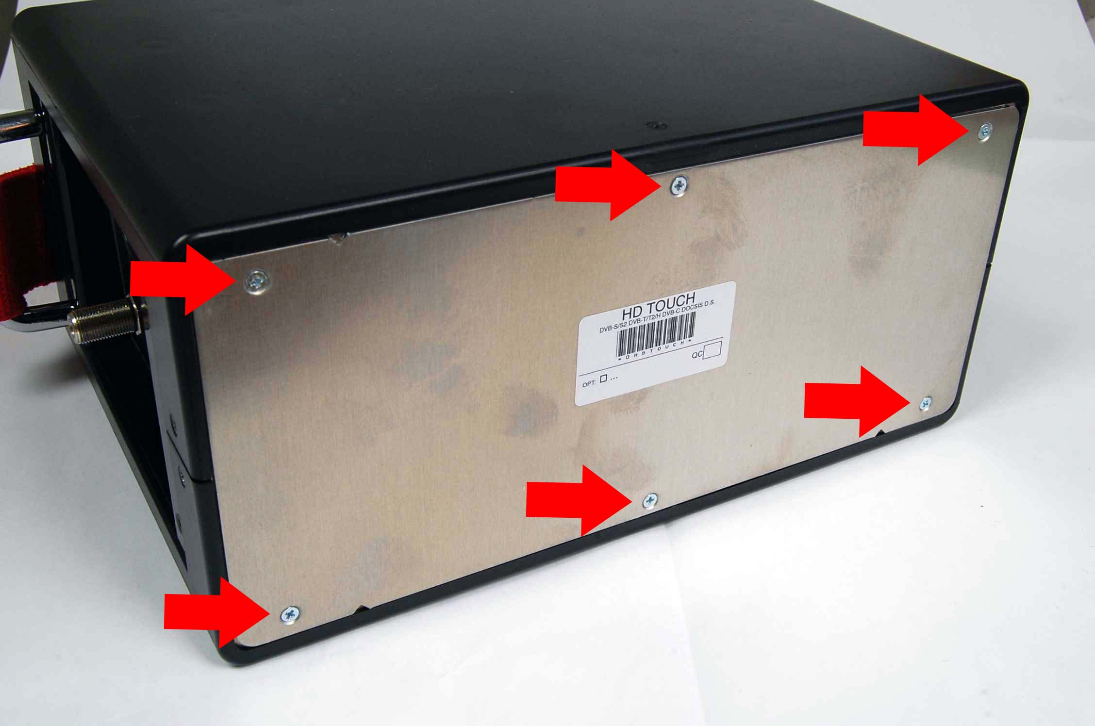
C ) Unscrew the 6 screws on the back cover “battery” with a suitable screwdriver (Figure 1);
D ) Unscrew the 6 screws on the top cover with a suitable screwdriver (Figure 2);
 |
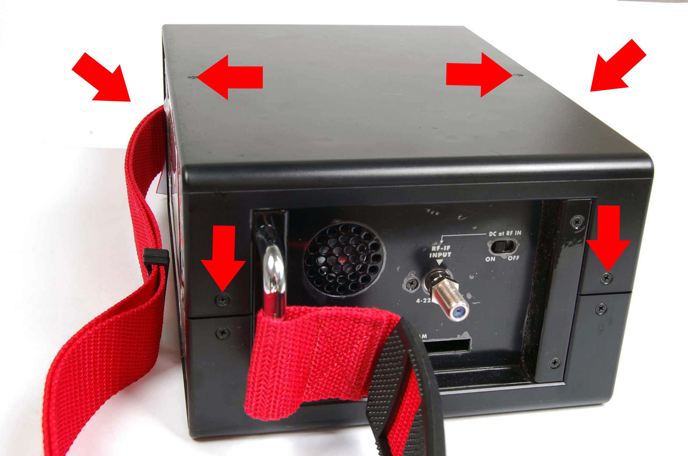 |
| Figure 1: Opening the battery area | Figure 2: Opening of the equipment |
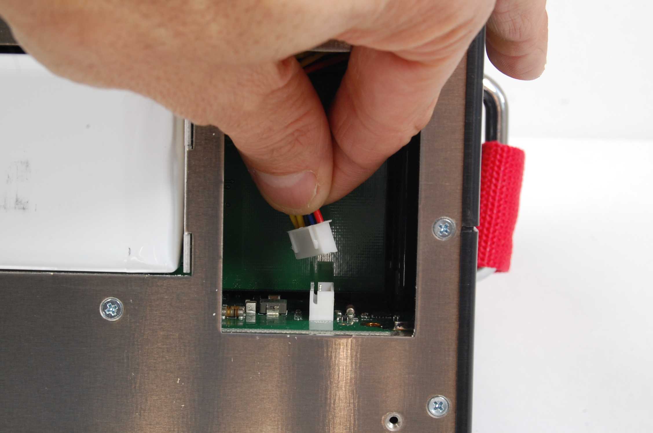
E ) Remove the BATTERY connector from the motherboard (no tools, just with your fingers) to prevent short circuits (Figure 3);
F ) Use the nails of the two index fingers (without any mechanical tool) to raise GENTLY the two side blocks of flat cable connector located on the display board of the DISPLAY (Figure 4);
 |
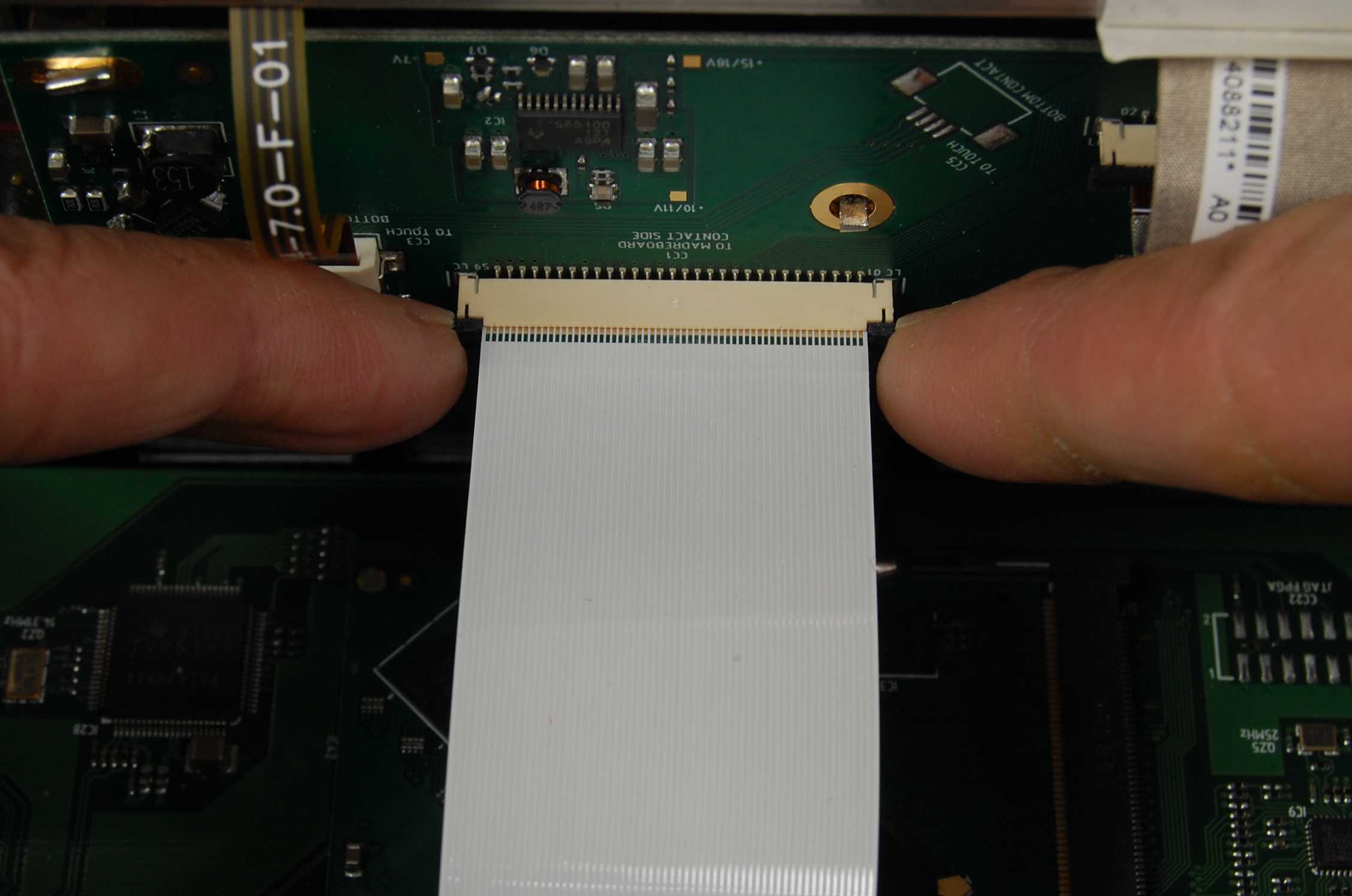 |
| Figure 3: Removing the battery connector | Figure 4: Release the connector safety blocks |
G ) Use your fingers only to GENTLY reinsert the flat cable of the display way down in its connector (Figure 5);
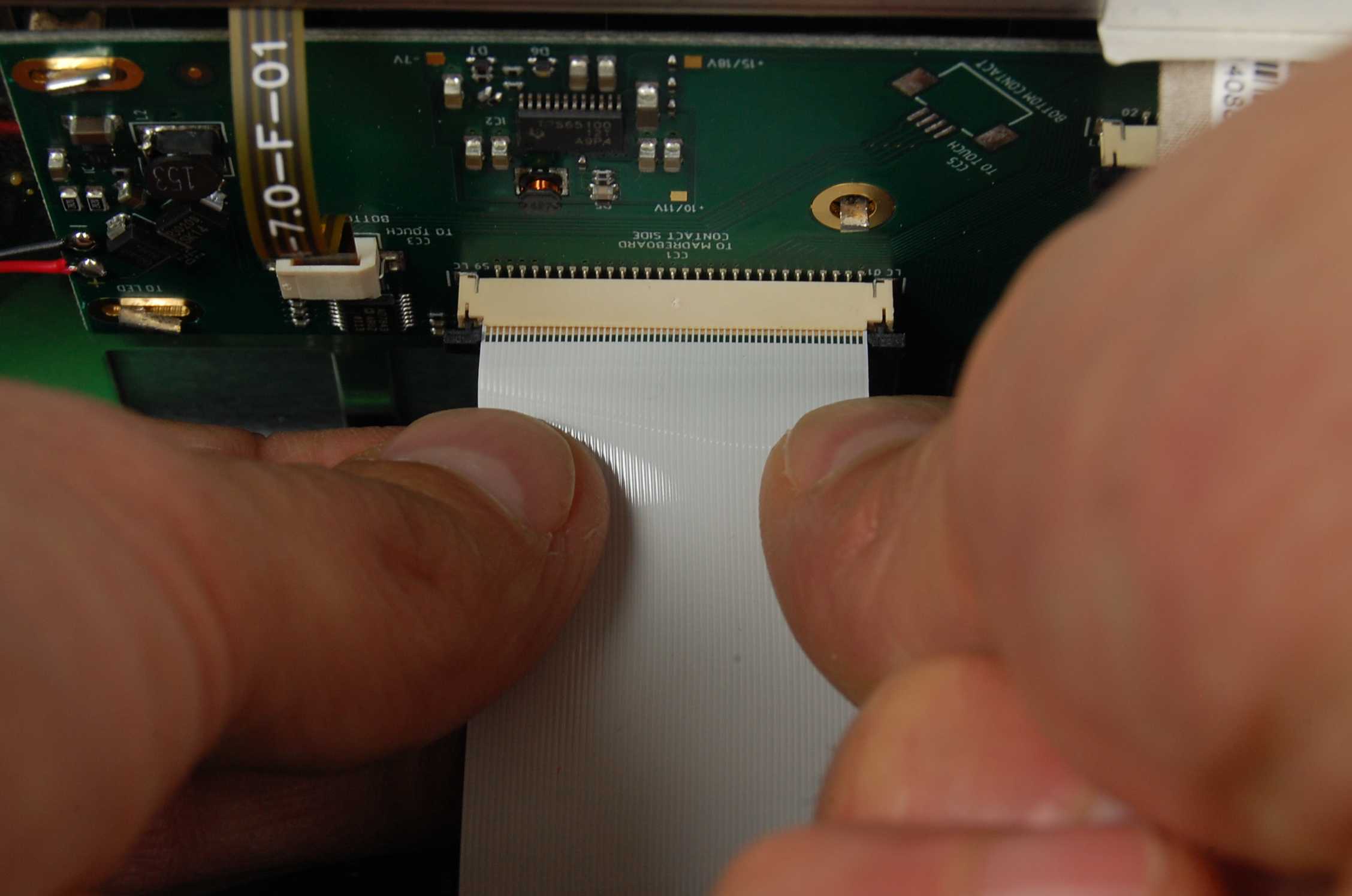
H ) Use only the nails of 2 thumbs to GENTLY close the connector safety bloks (Figure 6);
 |
 |
| Figure 5: Fully insert the flat cable | Figure 6: Hooking security block of the DISPLAY connector |
IMPORTANT: Do not use glue to secure the flat cable into the connector, it will irreparably damage the instrument.
H BIS) Repeat the steps described in point F, G and H to accommodate the other connector of the flat cable of the display placed on the card MOTHER (Figure 6 BIS);
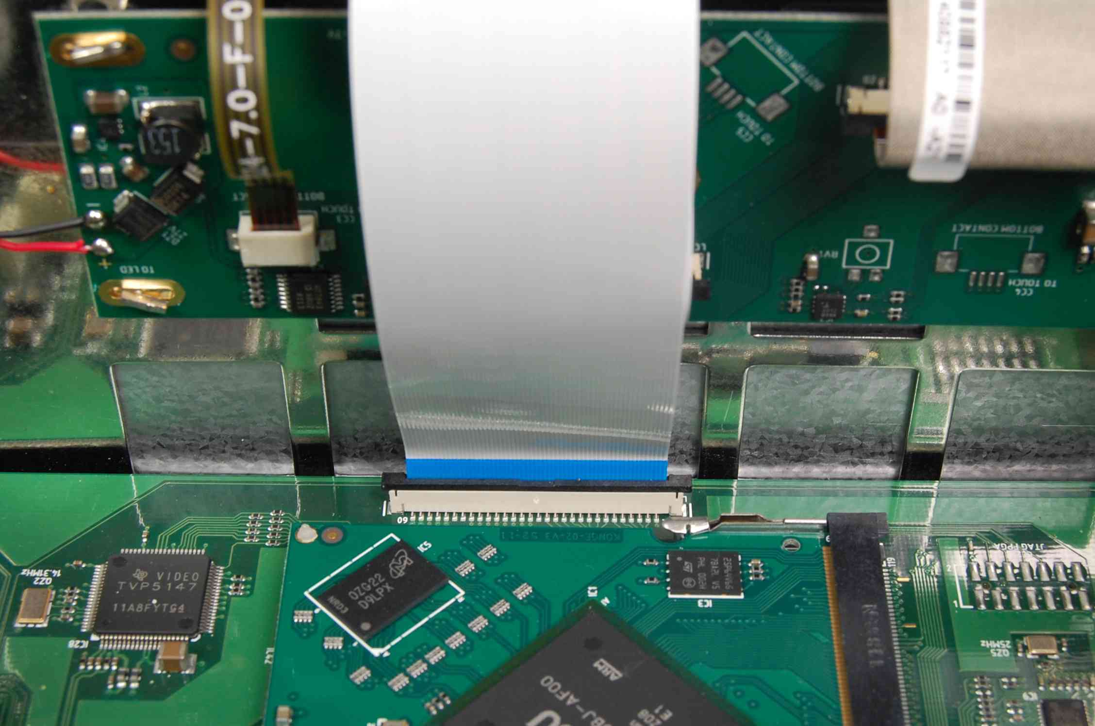 |
| Figure 6 BIS: Flat cable connector display tab MOTHER |
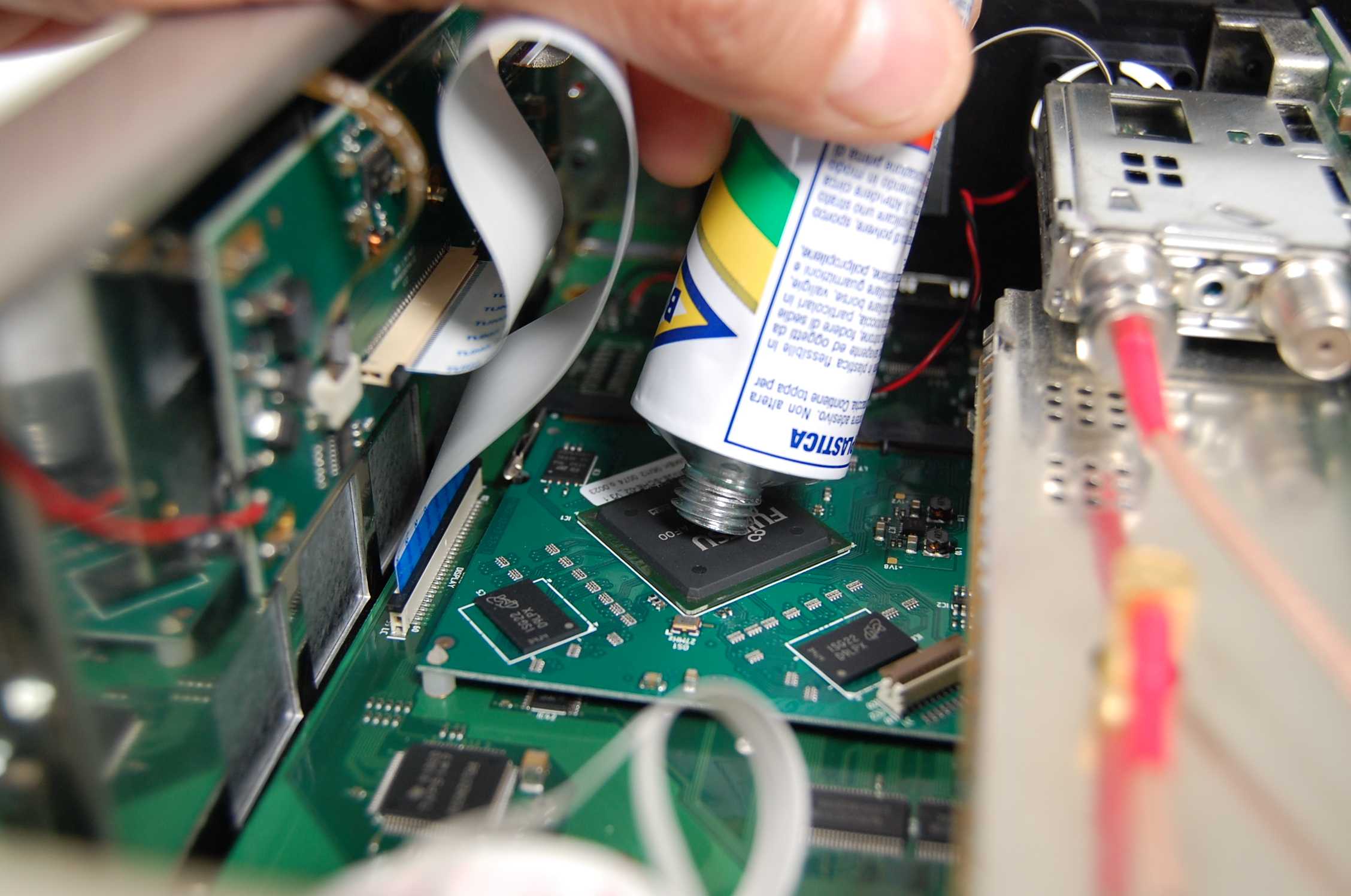
I ) Slightly lift the flat cable display and deposit a drop of adhesive glue for rubber (type BOSTIK NOT CYANOACRILATE) above the microprocessor, as shown in Figures 7 and 8;
 |
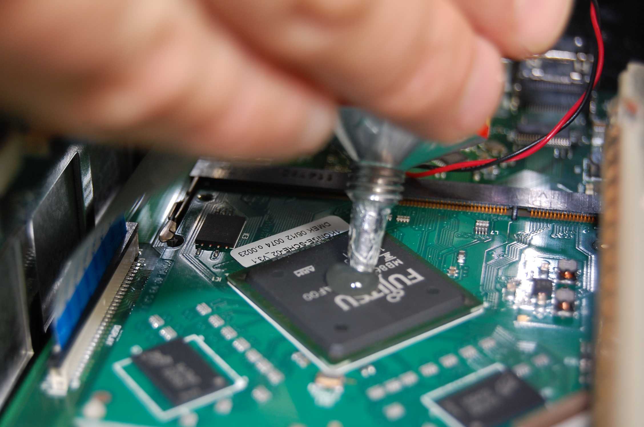 |
| Figure 7: Lift the flat cable to place a drop of glue Bostik (not cyanoacrylate) | Figure 8: Lift the flat cable to place a drop of glue Bostik (not cyanoacrylate) |
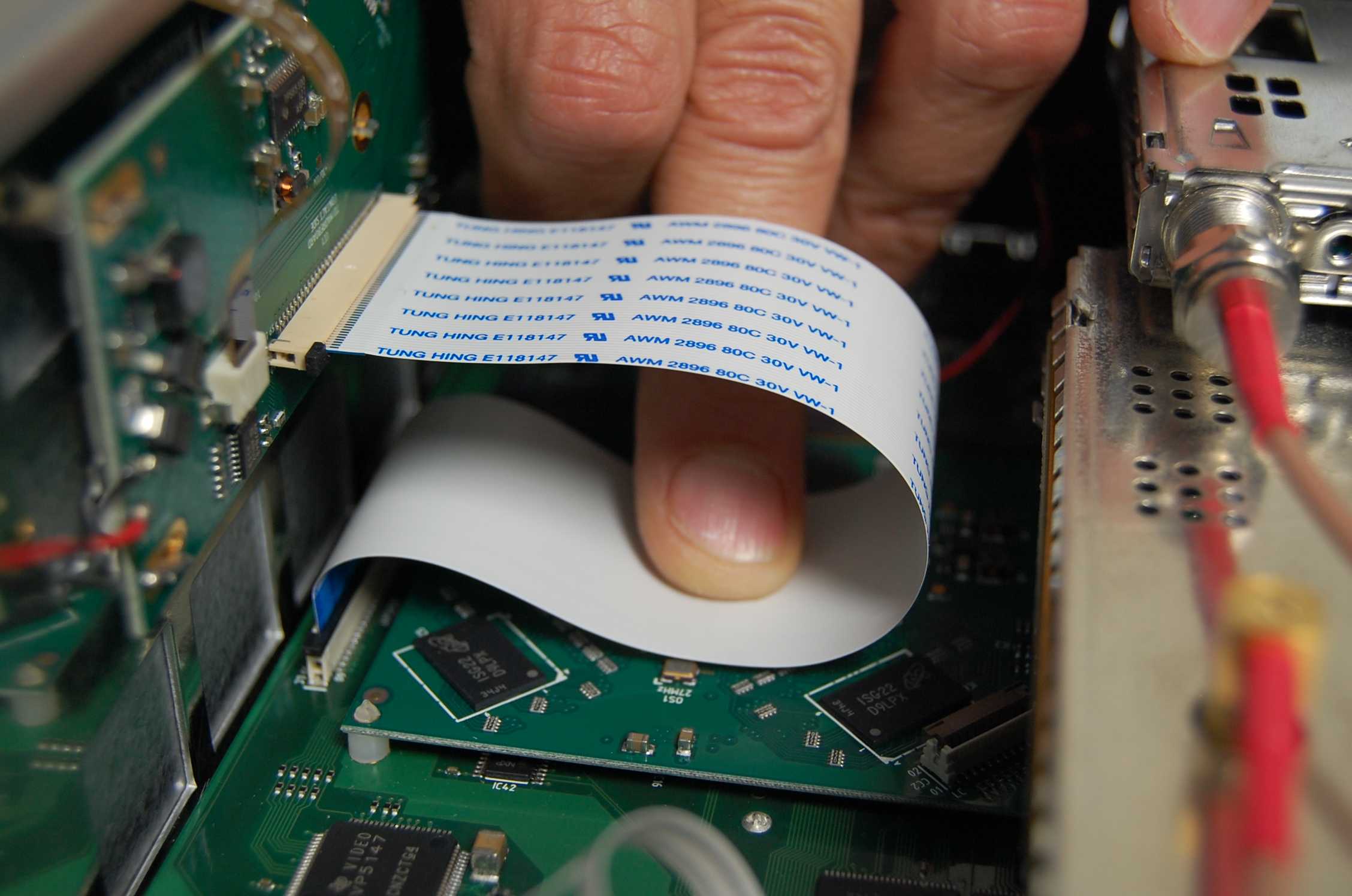
L ) Place the flat cable with soft curves as in Figure 9 and hold it in place with your finger for a few seconds to wait for the adhesive to bond;
M ) At the end, the flat cable will be fixed as shown in Figure 10;
 |
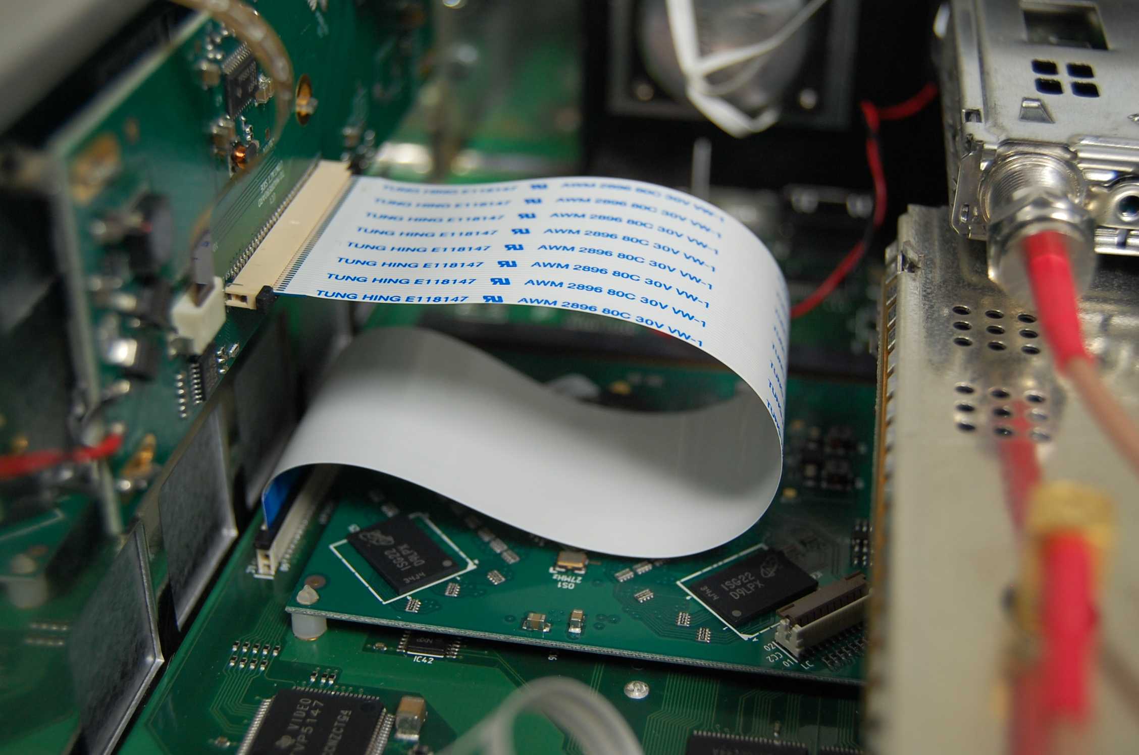 |
| Figure 9: Hold for a few seconds flat cable | Figure 10: Fixing completed |
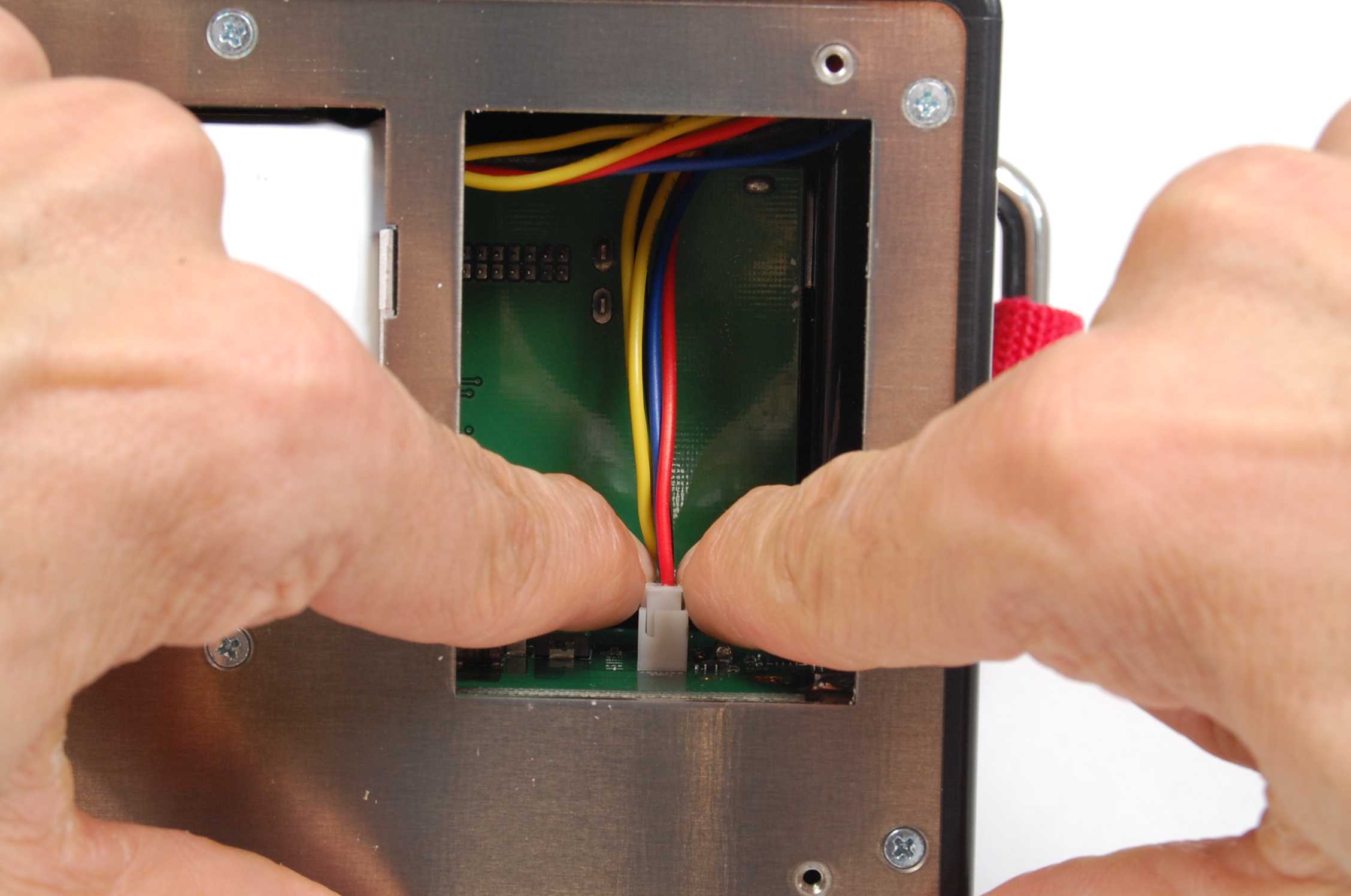
N ) Reconnect the connector BATTERY only with your fingers without tools (Figure 11) (the connector is polarized and has only one direction of entry), then testthe instrument, before close it;
O ) If everything is OK, turn off the instrument and GENTLY tighten the six screws of the rear cover “battery” (Figure 12);
 |
 |
| Figure 11: Inserting battery connector | Figure 12: Closing the battery area |
P ) Screw the 6 screws of the top cover to close the instrument (Figure 13);
Q ) Insert the instrument in the bag.
 |
| Figure 13: Closing the instrument |
R ) Turn on the instrument and verify proper operation.
Note: