If the instrument presents problems of navigation (turning the encoder does not vary the parameters), it may be some of the connecting wires, are disconnected
Important:
A ) Turn off the instrument;
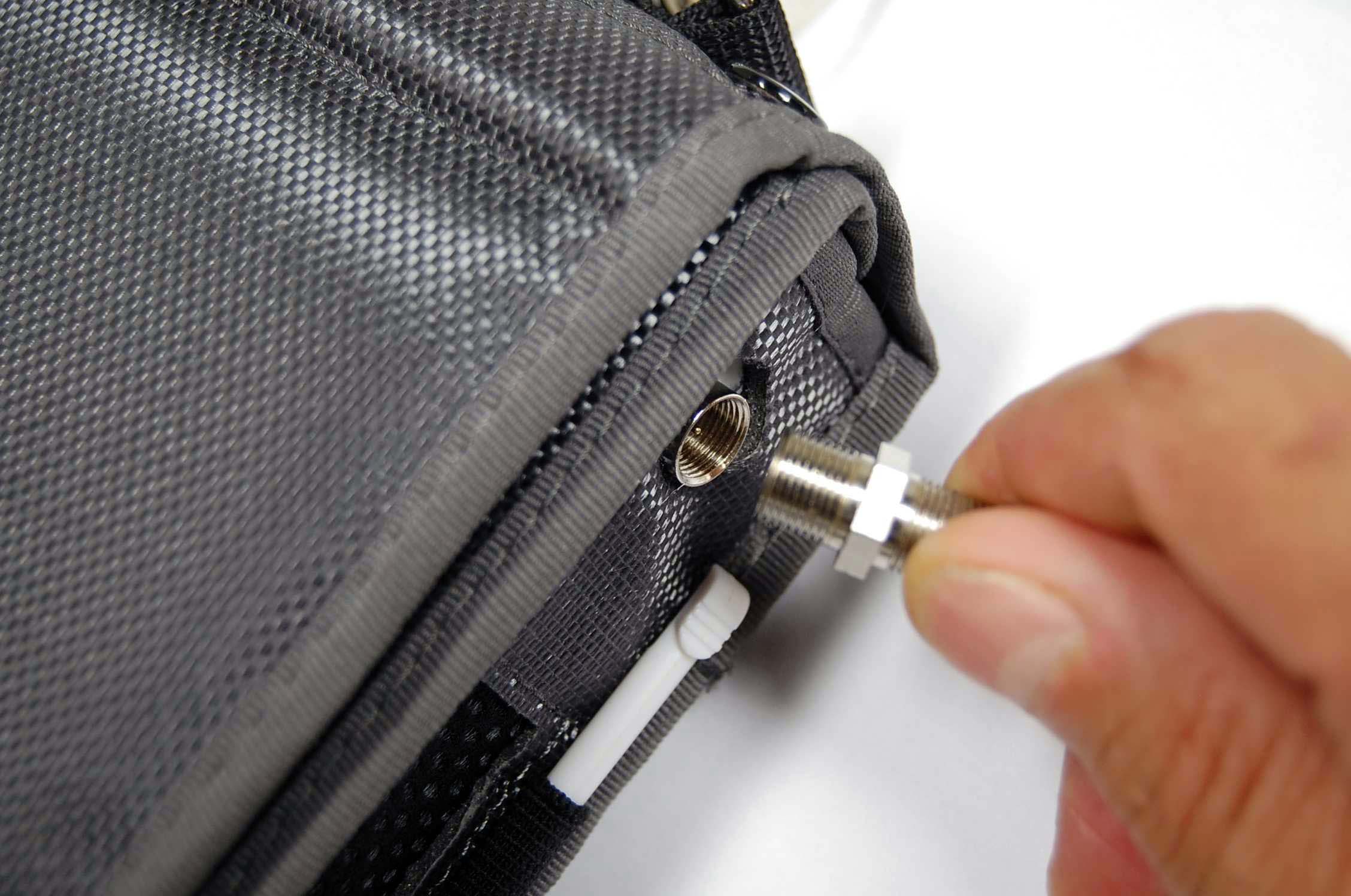
B ) Unscrew the RF input connector, female F / F female (Figure 1);
C ) Remove the instrument from the bag;
D ) Remove the 10 screws with a correctly screwdriver (Figure 2);
 |
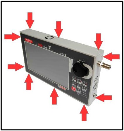 |
| Figure 1: Unscrew the RF input connector | Figure 2: Opening of the equipment |
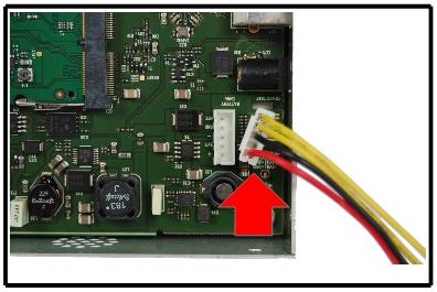
E ) Remove the BATTERY connector from the motherboard (no tools, just your fingers) to prevent short circuits (Figure 3);
F ) Use pliers to straighten 4 blocks cover safety of the TV tuner (Figure 4);
 |
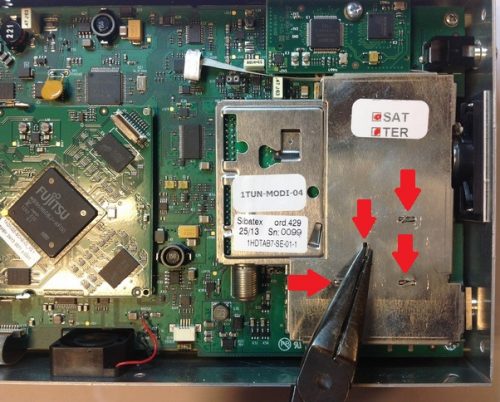 |
| Figure 3: Removing the battery connector | Figure 4: Release safety blocks cover TV tuner |
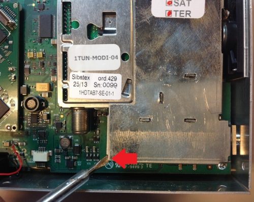
G ) Use a screwdriver to lift the cover of TV tuner (Figure 5);
H ) If the encoder is unscrewed and moves lock it with the thicknesses of plastic glued on the two sides shown in yellow between the metallic screen and the encoder (Figure 6);
I ) Restore the welds of the 5 wires terminal of the encoder with the motherboard (even those not yet disconnected) (Figure 6);
 |
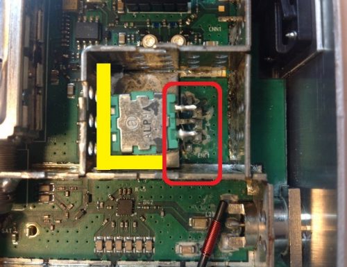 |
| Figure 5: Lifting the cover of TV tuner | Figure 6: Detail wires connecting encoders and yellow where to insert a hard plastic thickness well glued to mechanically lock the encoder |
L ) Close the cover of TV tuner;
M ) Use pliers to fold the 4 blocks cover safety of the TV tuner;
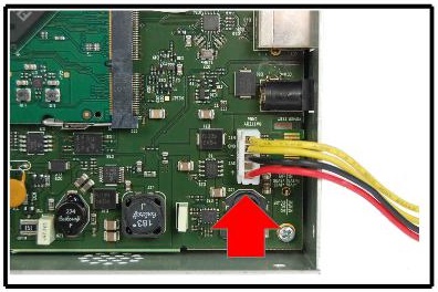
N ) Reconnect the BATTERY connector (only with your fingers without tools) (Figure 7) and try the instrument, before closing;
O ) If everything is OK, turn off the instrument and tighten the 10 screws of the cover to close the instrument (Figure 8);
 |
 |
| Figure 7: Inserting the battery connector | Figure 8: Close the instrument |
P ) Insert the meter in the bag;
Q ) Screw the RF input connector, female F / F female (Figura 9);
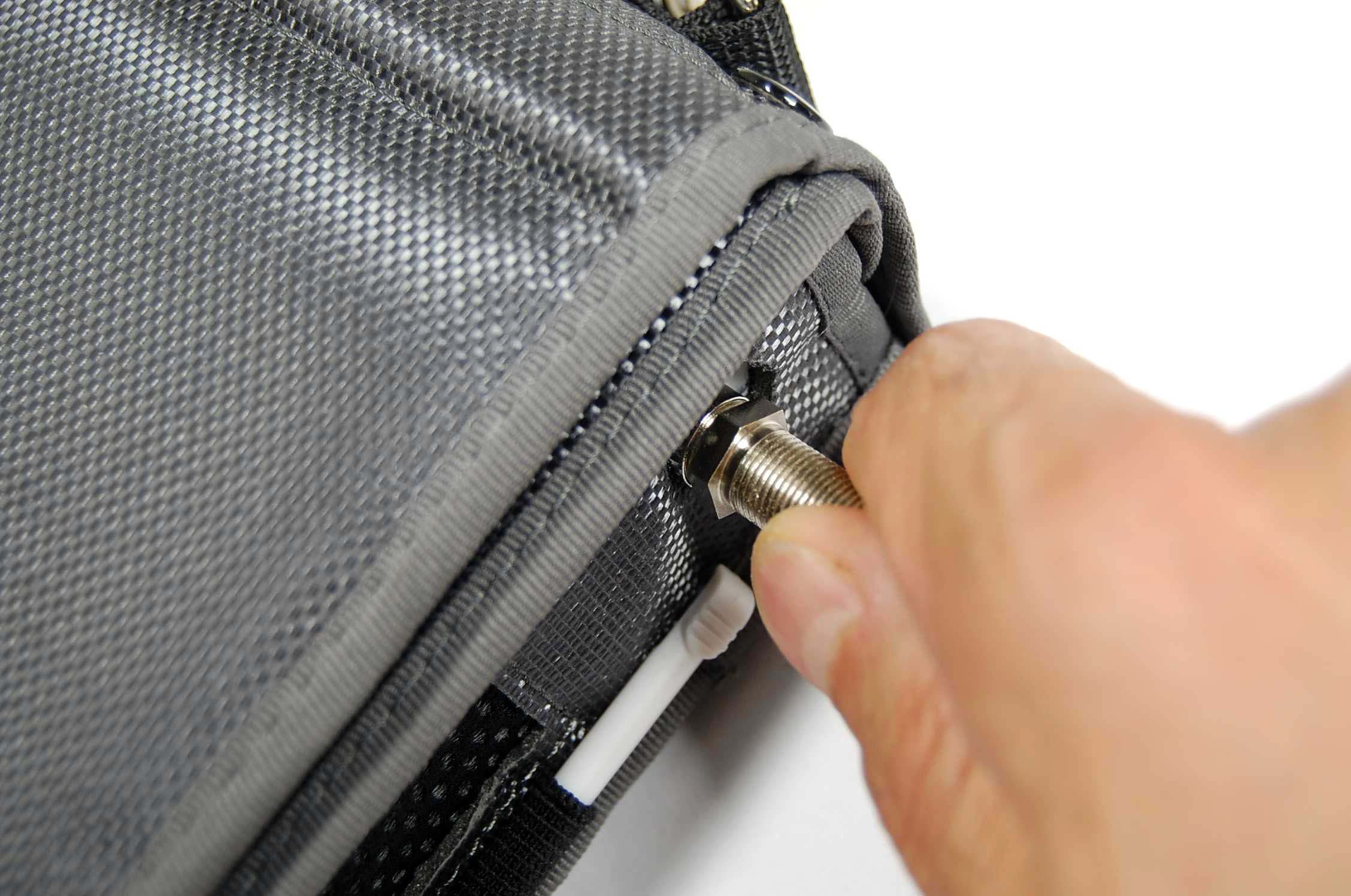 |
| Figure 9: Screw the RF input connector |
R ) Turn on the instrument and verify proper operation.
Note: