Important: Do not use any type off glue to secure the flat cable into the connector, it will irreparably damage the instrument.
If the instrument are having trouble viewing the display as listed on the title, check the correct insertion of the “flat cable of the display” in the connector of the motherboard.
Important: Do not move or enter the FLAT CABLE DISPLAY in its connector while the instrument is POWER ON.
A ) Turn off the instrument;
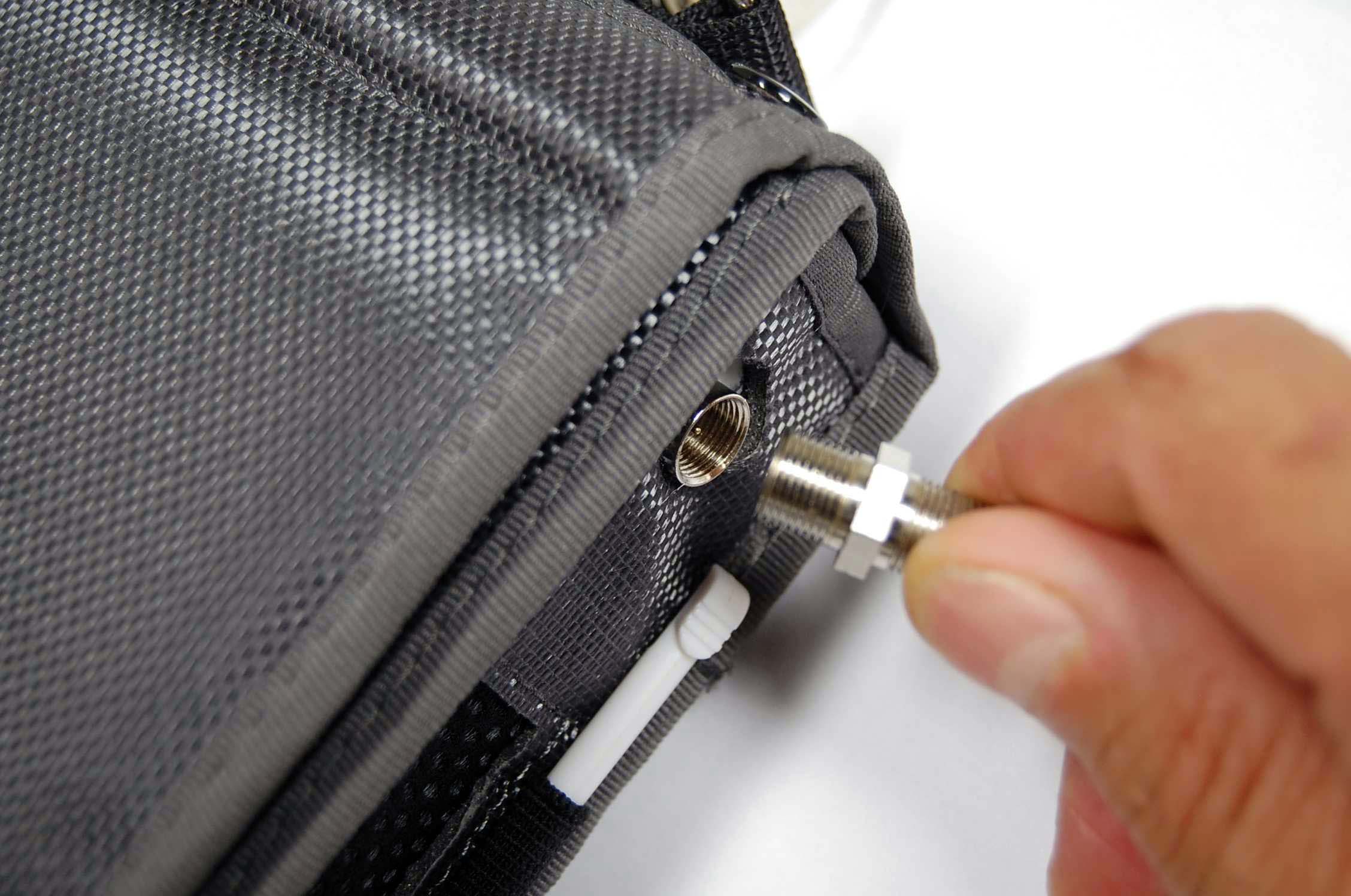
B ) Unscrew the RF input connector, female F/F female (Figure 1);
C ) Remove the instrument from the bag;
D ) Remove the 10 screws with a correctly screwdriver (Figure 2);
 |
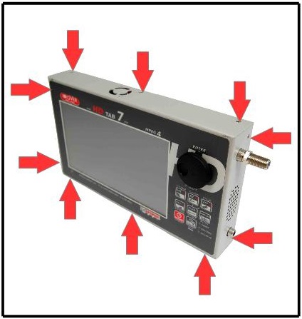 |
| Figure 1: Unscrew the RF input connector | Figure 2: Opening of the equipment |
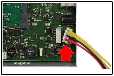
E ) Remove the BATTERY connector from the motherboard (no tools, just your fingers) to prevent short circuits (Figure 3);
F ) Use both hands index finger nails (without any mechanical tool) to raise GENTLY the 2 side blocks of the connector on the motherboard (Figure 4);
 |
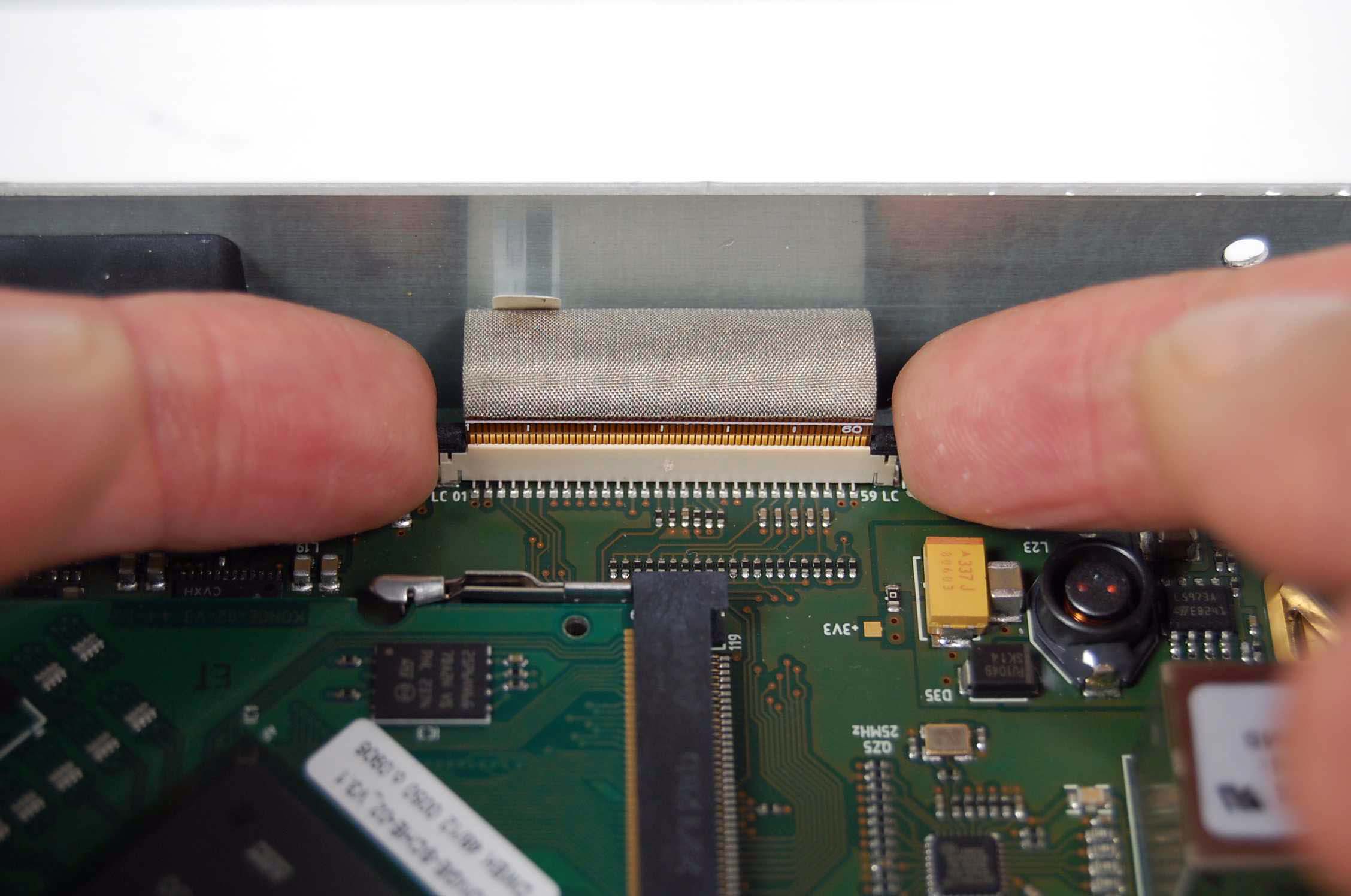 |
| Figure 3: Removing the battery connector | Figure 4: Block Release of connector security |
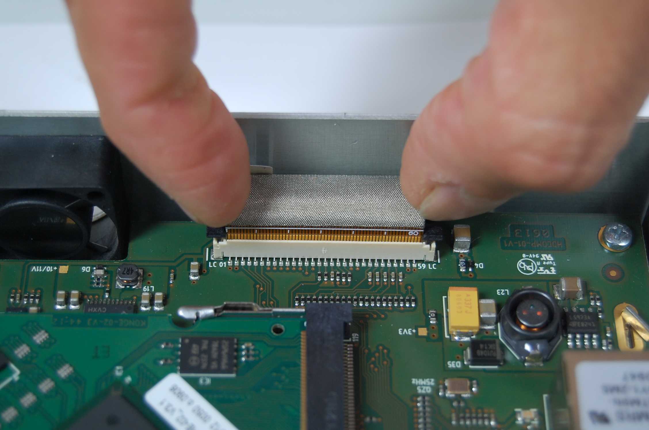
G ) Use your fingers to GENTLY re-enter the flat cable into the connector of the display up to the bottom (Figure 5);
H ) Use only the nails of the 2 thumbs to close GENTLY Safety blocks connector (Figure 6);
 |
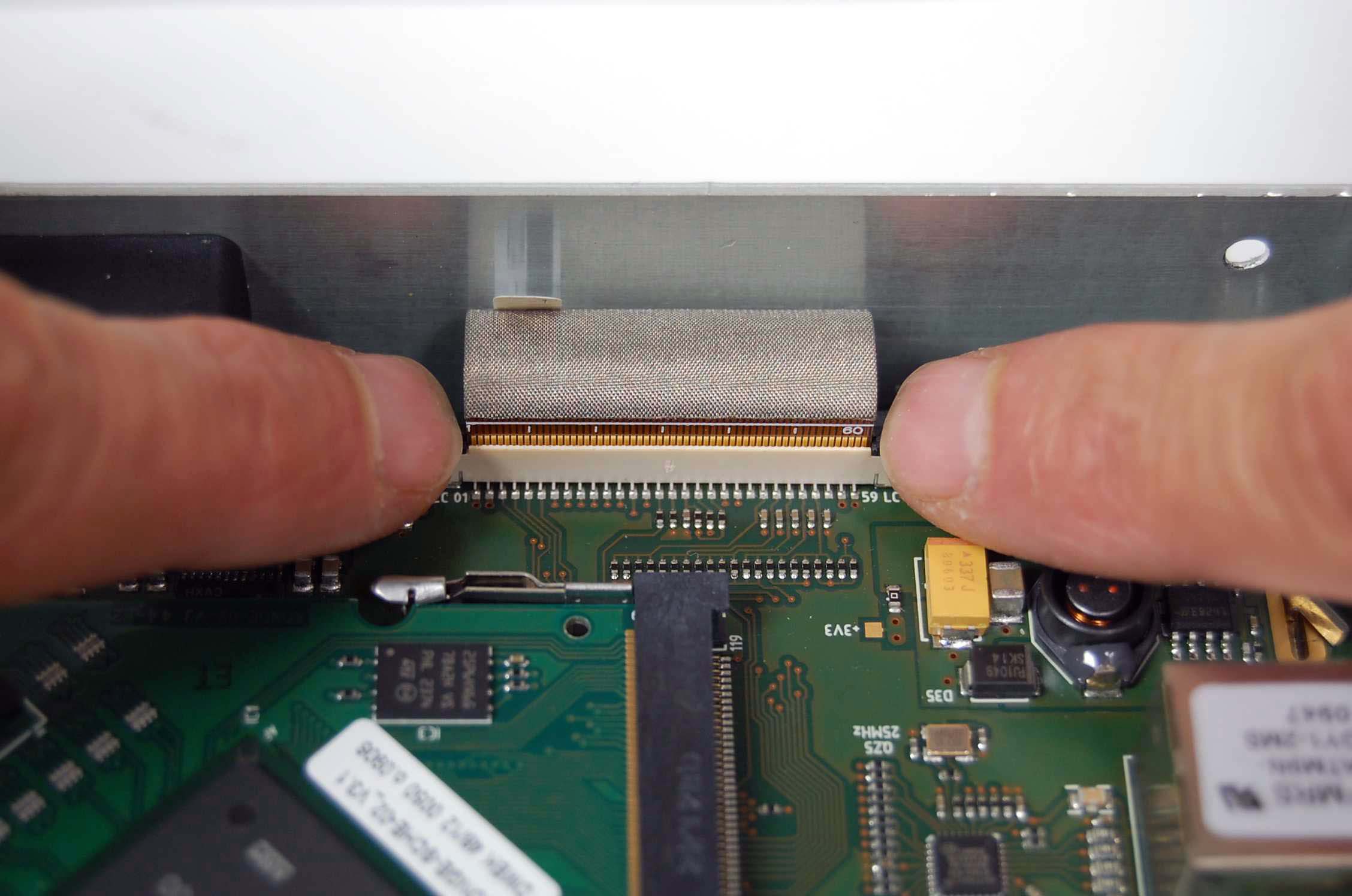 |
| Figure 5: Fully insert the flat cable | Figure 6: Hooking safety blocks display connector |
Important: Do not use any type off glue to secure the flat cable into the connector, it will irreparably damage the instrument.
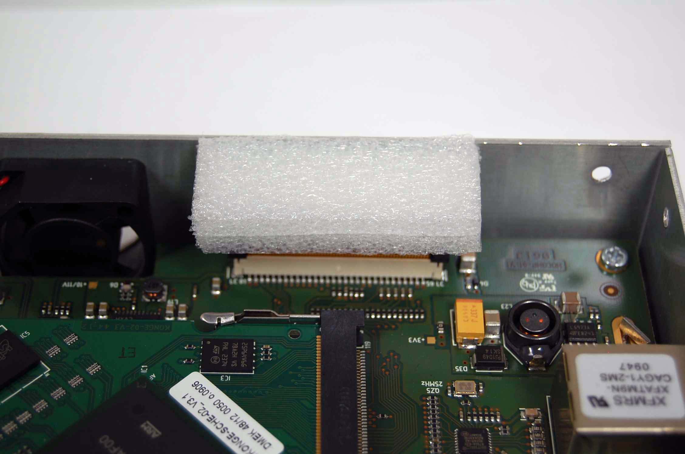
I ) Insert a thickness of compact polystyrene as shown in Figures 7 and 8, so that the cover takes pressed the flat cable in its connector;
 |
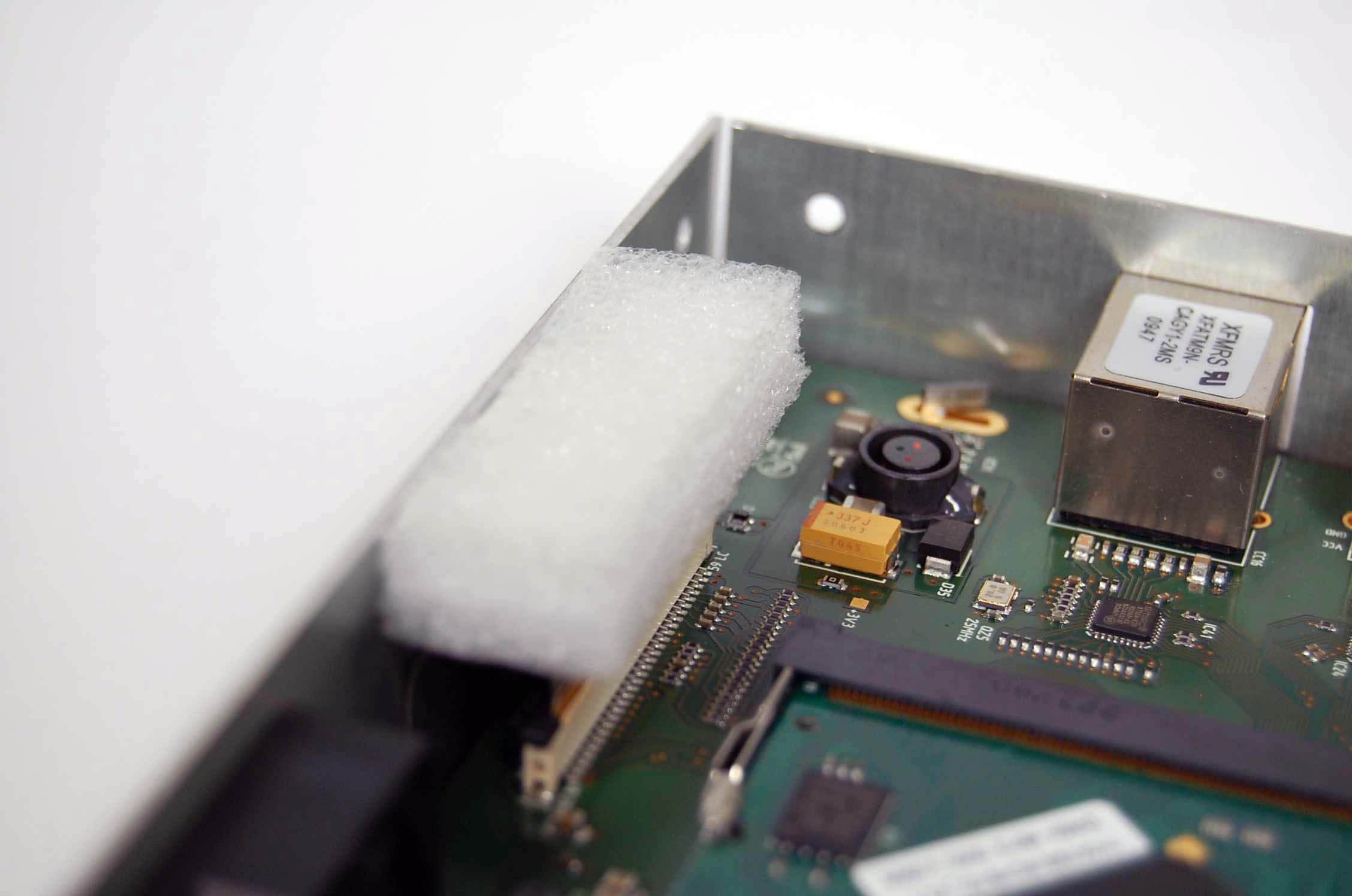 |
| Figure 7: Thickness of compact polystyrene | Figure 8: Thickness of compact polystyrene |
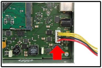
L ) Reconnect the BATTERY connector only with your fingers without tools (Figure 9) and try the instrument, before clasing;
M ) If everything is OK, turn off the instrument and tighten the 10 screws of the cover to close the instrument (Figure 10);
 |
 |
| Figure 9: Inserting the battery connector | Figure 10: Close the instrument |
N ) Insert the meter in the bag;
O ) Screw the RF input connector, female F / F female (Figure 11);
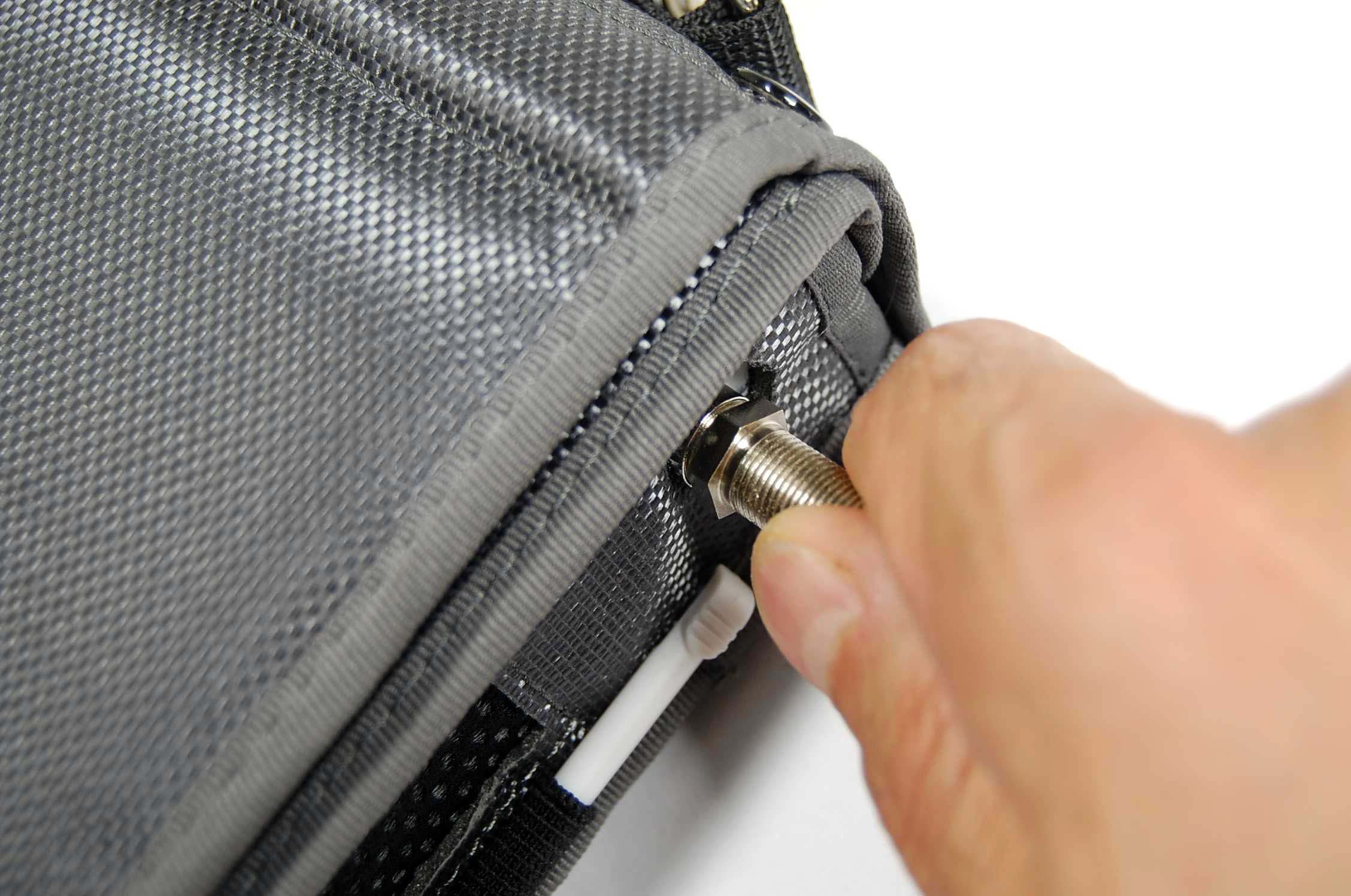 |
| Figure 11: Screw the RF input connector |
P ) Turn on the instrument and verify proper operation.
Note: