GENERAL DESCRIPTION:
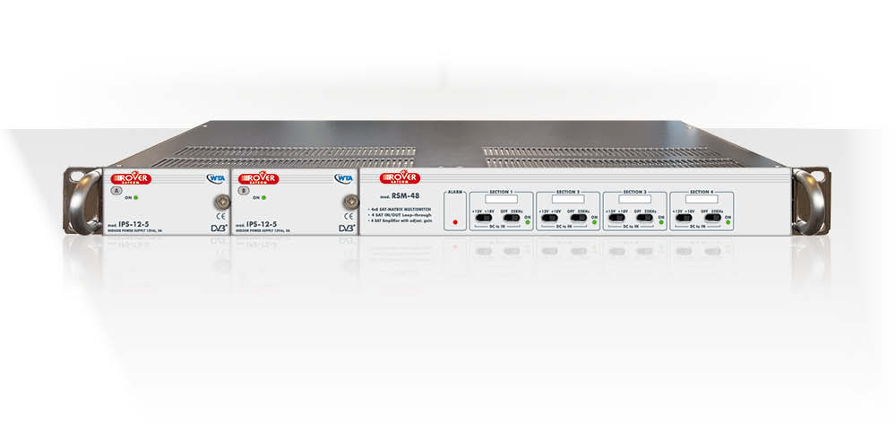
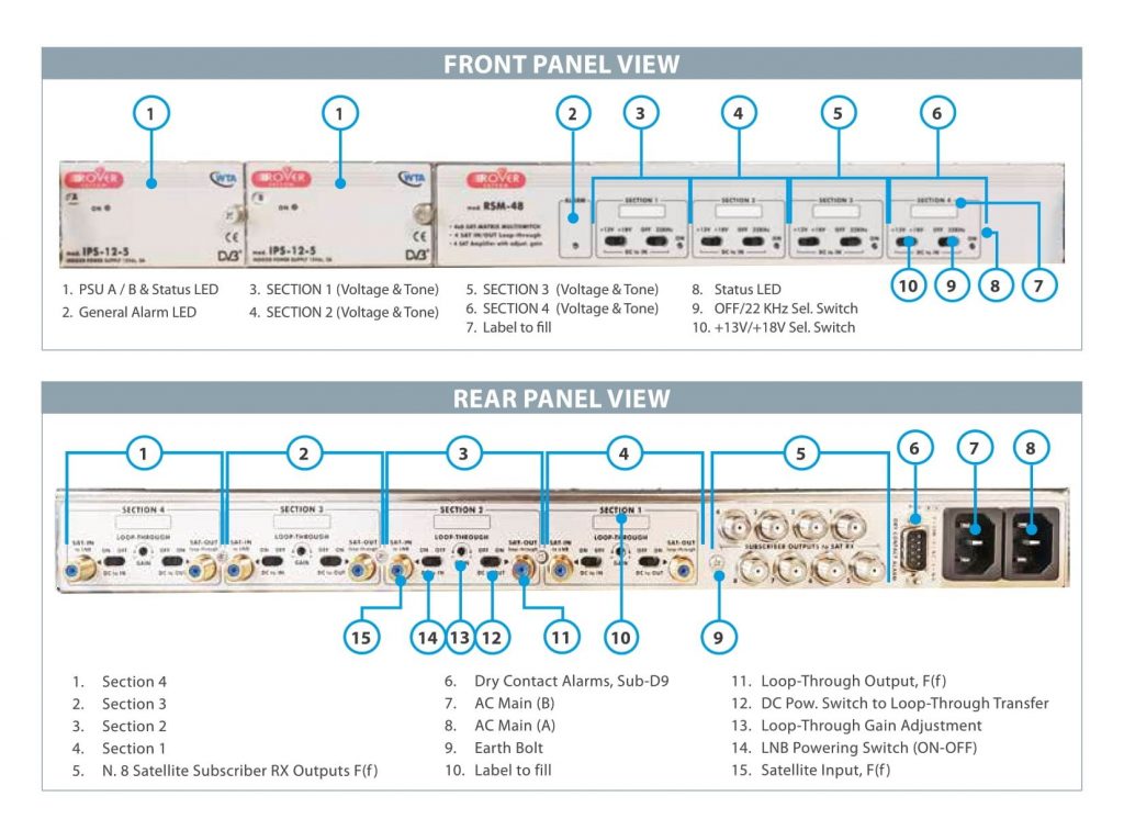
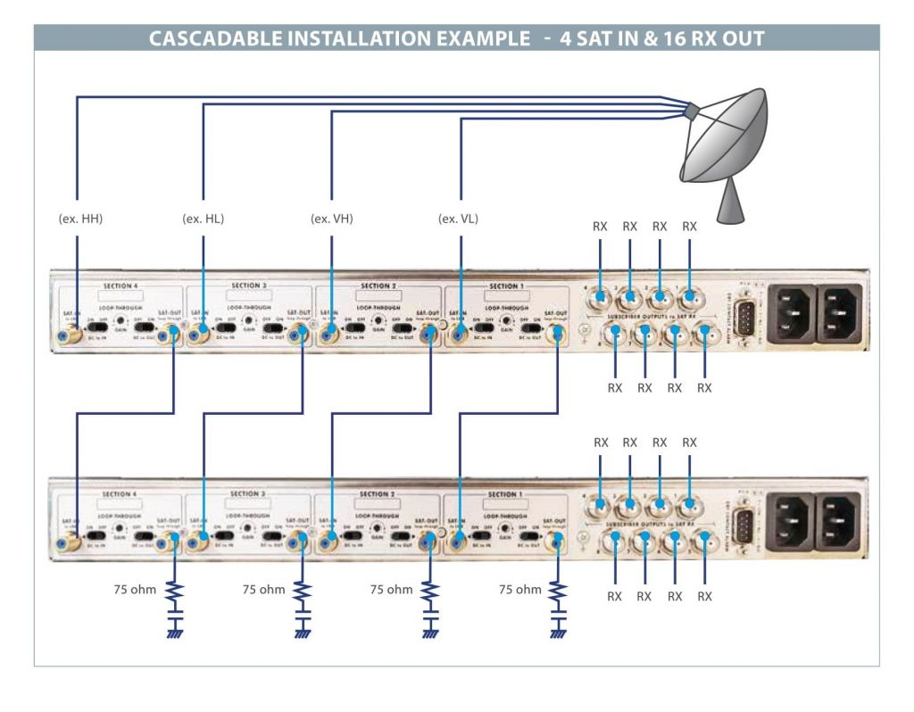
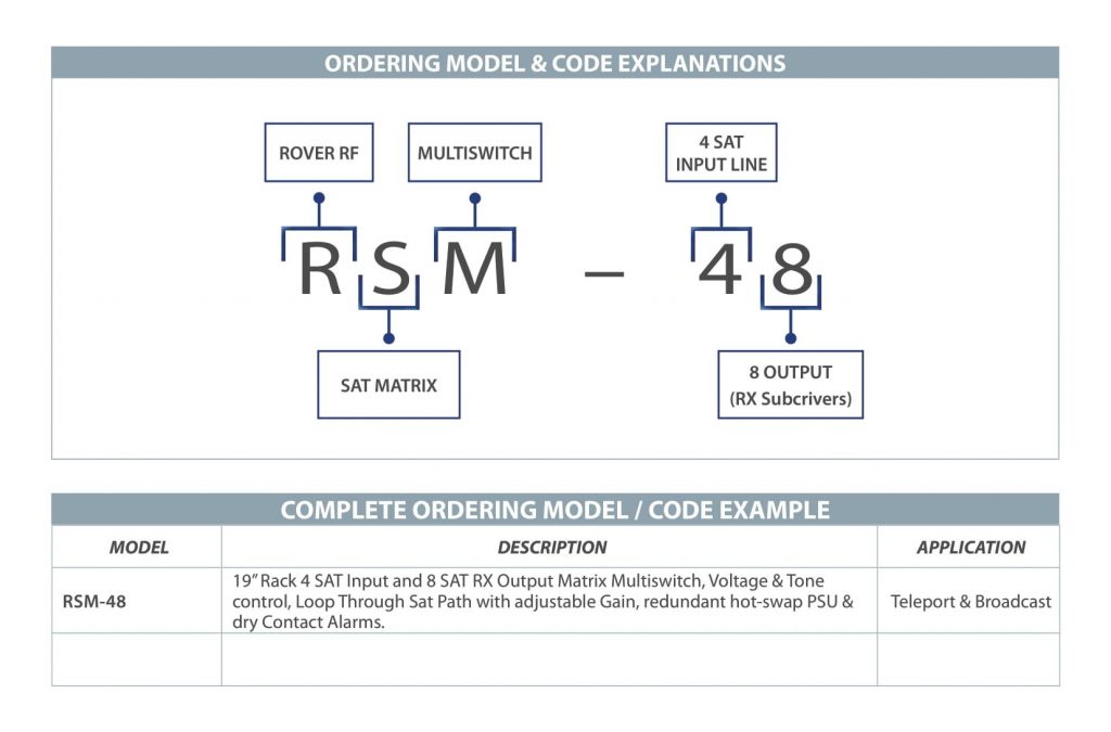
- 4 Satellite Inputs (HL, VL, HH & VH) with LNB Voltage & Tone
- 8 Subscriber RX Outputs, Input Selection via Voltage & Tone
- Loop-Through Output per Satellite Polarity providing Variable Gain
- DC Powering Transfer via Loop-Through Path
- Frequency Range = 950-2150 MHz (up to 2400 MHz)
- Connectors = F(f )
- Impedance = 75 Ohm
- LNB Pow. at SAT-IN = 13/18 V, Max. 500 mA each
RF SPEC – SAT-IN to SUBSCRIBER OUT:
- Gain = 2 dB
- Full Band Flatness = ±2 dB (with 1,5 dB positive Slope)
- Transponder Flatness = 0,5 dB (36 MHz Bandwidth)
- Isolation OUT-OUT = >35 dB, typ. 42 dB
- IMD = 40 dB (2 Tones at -13 dBm)
- Output Level = max 90 dBμV (-18 dBm) @30carrier
- Return Loss = 14 dB typ.
- Noise Figure = 8 dB
RF SPEC – SAT-IN to SAT-OUT (LOOP THROUGH):
- Gain = 15 dB adjustable Gain
- Isolation OUT-OUT = >45 dB, typ. 50 dB
- Full Band Flatness = ±1 dB (with 4 dB positive Slope)
- Transponder Flatness = 0,5 dB (36 MHz Bandwidth)
- IMD = 40 dB (2 Tones at -13 dBm)
- Output Level = max 90 dBμV (-22 dBm) @30carrier
- Return Loss = 19 dB typ.
- Noise Figure = 8 dB (at Max Gain)
RX SUBSCRIBER PORT CONTROL:
- Section 1 Input (ex. VL) Selection = 13 V / 0 kHz
- Section 2 Input (ex. VH) Selection = 13 V / 22 kHz
- Section 3 Input (ex. HL) Selection = 18 V / 0 kHz
- Section 4 Input (ex. HH) Selection = 18 V / 22 kHz
DRY CONTACT ALARMS:
- SUB-D9 Connector at the Rear (with PIN descript.)
- Relay Contact Load = 65 V / 400 mA
- General Alarm for:
– LNB Voltage Short Circuit
– PSU Failure
– One Power Line Failure
PLUG-IN POWER SUPPLY:
- Hot-Swappable PSU’s from the Front
- DC 12 V, 5 A
- 2 AC Receptacles from 2 independent Power Lines
- AC Input Range = 110 to 240 VAC
- Power Consumption = <25 VA
GENERAL SPECIFICATIONS:
- Size = 1 RU 19“, 320 mm deep
- Net Weight = <4 kg
- Safety = EN50083-1 & EN60950
- EMC = EN50083-2
- Env. Conditions = -30°/+55°C (Max 60°C)
- Humidity = Max. 95 %


