L-Band Dual Redundancy RF Switching System

RFS8-X-X

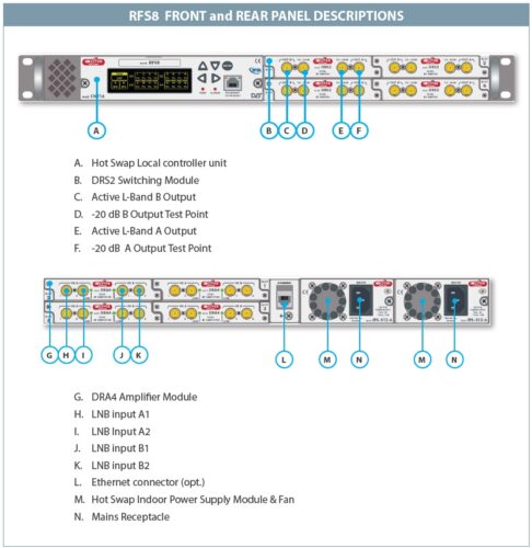
19” Rack Hot-Swap Extended L-Band amplifier and switching modules 700-3000 MHz

  •  SCALABLE AND MODULAR
    • UP TO N. 4 HOT SWAP QUADRUPLE AMPLIFIERS MODULES
    • UP TO N.4 HOT SWAP DUAL RF SWITCHING MODULES
    • RF FREQ. 700 -3000 MHZ
    • RF POWER MONITORING
    • MEETS OIP-3, RL AND FLATNESS STRINCT SPECIFICATIONS
    • HOT SWAP REDUNDAND PSU 1:1
    • FULL LNB POWERING
    • CONFIGURABLE VIA LOCAL DISPLAY AND KEY BOARD
    • MONITORING AND CONTROL VIA WEB GUI & SNMP

RFS8 is a 19” Rack EXTENDED L-BAND LINE AMPLIFIER & REDUNDANCY RF SWITCHING SYSTEM.

The RFS8 Rack interfaces up to 8 MAIN and 8 BACKUP L-BAND signals with monitoring capabilities to
switch to a backup signal with a programmable RF power threshold.

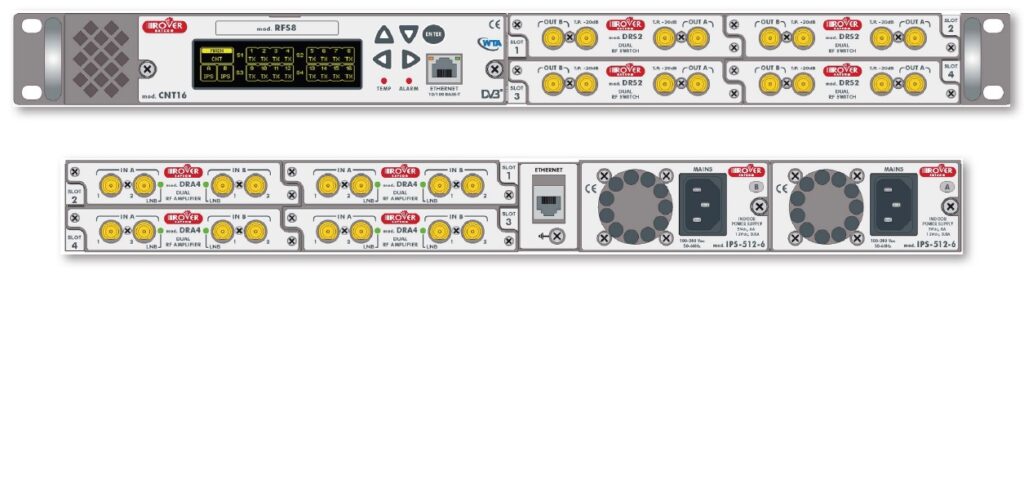
This system has a Split architecture to reduce assembly and maintenance costs. Built with N.4 HOTSWAP
modules on the rear side of the chassis (DRA4), having n. 4 L-Band Amplifiers each and with
N.4 HOT-SWAP modules on the front side of the chassis (DRS2), having n.2 switches to automatically
provide the proper RF output for each couple of L-Band input signals.

The double redundant PSU intelligent technology allows an immediate switch on the secondary
power source.

This technology ensures continuous quality of service and the hot swap Modules can be easily
replaced by the local personal.

An advanced monitoring system provides all measurements and alarms locally or remotely via WEB
or SNMP. Ideal for Professional use, like Redundancy, Distribution & Monitoring, these are currently
the best value for money.

DRA4 TECHNICAL SPECIFICATIONS

RF SPECIFICATIONS:

  • Freq. Range = 700-3000 MHz
  • Positive Gain Slope = 4 dB
  • Gain range = 15 dB
  • Noise Figure = 7 dB
  • Connectors = F, BNC or SMA
  • Impedance = 75 or 50 Ohm
  • RF INPUT Level Range = – 5 to – 50 dBm
  • Damage Input Level = > + 10 dBm
  • Input R.L. = 16 dB typ., 14 dB min.
  • Output R.L. = 16 dB typ., 14 dB min.
  • Output Frequency Responce = ± 1,5 dB Max

LNB POWER CONTROL:

  • D.C. VOLTAGE = OFF, 13V, 18V max 500 mA for each Input
  • TONE = 22 KHz ON/OFF
  • LNB Protections = short circuit and current limited
  • LED = green = OK, red = dc short circuit Alarm

RF POWER SENSING ALARM:

  • POWER THRESHOLD = adjust from -50 to -5 dBm

POWER SUPPLY (for each amplifier):

  • 12 V d.c., 150 mA per module


DRS2 TECHNICAL SPECIFICATIONS

RF SPECIFICATIONS:

  • N. 2 Switching units per module with 2 WAY RF
    Output Switch (700-3000 MHz)
  • «F» Output Connector (opt. SMA-BNC)
  • Automatic and Remote Control

RF MONITORING PORT for each Switch:

  •  On Front Panel -20 dB
  •  Connector = F or SMA
  •  Impedance = 75 or 50 Ω
  •  Flatness = ± 2 dB

UNIT TECHNICAL SPECIFICATIONS

GENERAL SPECIFICATIONS:

  • SAFETY = EN 50 083-1 and EN 60 950.
  • ENVIRONMENT:
    – Temperature range: –30° / + 55° (max 60°)
    – Umidity 95%
  • EMC = EN 50 083-2

POWER SUPPLY (Redundant):

  • 2 x 220 Vac with FAN ventilator
  • Controller unit: Hotswap controller with local display
    and keyboard

SIZE & WEIGHT:

  • 19” 1U Rack chassis, 2.5 Kg

ROVER SATCOM - Equipment Index V8_5-01

Download